 |
| December 10, 2013 | Volume 09 Issue 46 |
Designfax weekly eMagazine
Archives
Partners
Manufacturing Center
Product Spotlight
Modern Applications News
Metalworking Ideas For
Today's Job Shops
Tooling and Production
Strategies for large
metalworking plants
Engineer's Toolbox:
Low-inertia, zero-backlash gear design for timing-critical applications
By Georg Bartosch, Intech Corp.
When one of our customers introduced a new machine for corrugating paper products, they came to us with a critical dilemma. How could they maintain precise timing between two shafts with corrugating steel teeth to prevent them from smashing into each other? To find a solution, we focused on backlash-free, low-inertia gear design.

Traditional split design backlash-free spur gears.
The traditional backlash-free gear design consists of two gears, typically spur gears -- one split in two halves. Once both gears are installed on the shaft, the two halves of the split gear are rotated manually in opposite directions until both touch the opposite tooth flanks of the wider mating gear, thus eliminating any backlash. The two narrower gears are fastened together, usually by means of bolts.
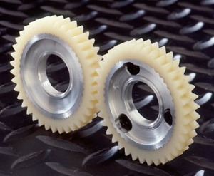
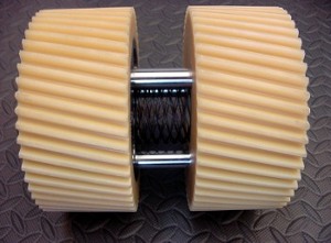
The Intech zero-backlash design rests on the same principle of eliminating backlash by engaging the opposing flank of a wider gear with two halves of a split gear. The gears are helical, but rather than rotating the narrower gears around their axis they are being forced apart in an axial direction. This is accomplished by: 1) a spring placed axially between the split gears, and 2) cylindrical guiding pins that are securely anchored in the metal core of one of the narrower gears fitting into the counter bores machined into the all-plastic second half of the split gear. The spring force pushes the gears apart, and the pins force the gear to move axially, preventing any rotation.

The Intech Power-Core helical gear design uses split helical gears pushed in opposite directions by a spring and guided axially by fixed pins. This design eliminates backlash by preloading the split gear in opposite flanks of the mating gear. (Note: Mating gears not shown.)
The principle is simple. One half of the split gear engages the wide gear on the load-carrying flank (the front flank). The other half, being guided by the pins to move axially, is brought to a stop by the rear flank of the second tooth "blocking" the axial movement with the helix angle.
For the preload of the split gear in opposing directions, we are relying on the elasticity of the Power-Core material. Intech Power-Core gears are made from cast nylon 12 with integral metal core. When pressed against the helical flank of the wider gear, the tooth of the narrower gear will deform slightly to allow engagement along the full length of the flank. Both halves of the split gear, as well as the spring load, are calculated to develop enough preload to carry the entire torque with enough safety to guarantee a backlash-free mesh -- even during an emergency stop. Intech uses proprietary software to calculate expected gear life.
For installation, and for gear hobbing prior to that, the two halves of the split gear are fastened together with the provided bolts, forming a perfect helical gear. This gear is then installed on the shaft and meshed with the wider helical gear. The gear half of the split gear, with the metal hub, is attached to the shaft (e.g. by means of a keyway and a key). Once the installation of all gears is complete, the fastening bolts are removed and the spring does the rest. With this design, the backlash adjustment is "automatic" because the spring pressure is permanent, and there is no need for manual readjustment when a tooth wear occurs.
By designing all gears in the gear train with the Intech Power-Core, we reduced inertia in the drive by 65 percent.
Learn more at www.intechpower.com.
Published December 2013
Rate this article
View our terms of use and privacy policy
