 |
| May 27, 2014 | Volume 10 Issue 20 |
Designfax weekly eMagazine

Archives
Partners
Manufacturing Center
Product Spotlight
Modern Applications News
Metalworking Ideas For
Today's Job Shops
Tooling and Production
Strategies for large
metalworking plants
Engineer's Toolbox:
Can you handle the ultimate teardown?
Viatran uses Design for Manufacture and Assembly to radically reduce part count, cut assembly time, and reimagine pressure transmitter design. Can your products handle this kind of scrutiny?
Sensitive, yet tough. That's the the job description of the hammer-union pressure transmitter used in oil and gas well-servicing applications like cementing, fracturing, and acidizing. This fine-tuned sensor must accurately and repeatably measure the hydraulic and pressure characteristics of drilling fluid in the harsh environments found in the secondary oil and gas recovery industry.
Withstanding mud, corrosion, vibration, humidity, and temperature extremes -- and the routine shock of hammer blows during installation -- the unit plays a pivotal role in communicating with downhole measurement-while-drilling (MWD) tools to help ensure safety and efficiency in the production environment. The unit's reliable performance is critical to the integrity of hammer-wing-union fittings used in thousands of energy installations around the globe [see sidebar at end of article].
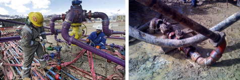
Figure 1: Hammer blows during installation (left) and extremes of dirt and moisture (right) characterize the tough working environment of the hammer-union pressure transmitter.
The world leader in sales of the component is the Viatran business unit of Dynisco, a Roper Industries company, whose model 510 Hammer Union pressure transmitter has been an industry staple for years. With a number of competitors vying for position in the supplier arena, Dynisco decided to take a renewed look at their core product to ensure that their lead would hold. Seeking to make the newest model a clear standout above the rest, they launched a redesign project with the goal of providing functional improvements that customers would respond to, along with increased assembly efficiency and cost effectiveness.
Begin it with benchmarking
A company-wide philosophy of continuous improvement has led Dynisco to emphasize the role of early design evaluation in its product development process. Knowing the value of applying Design for Manufacture and Assembly (DFMA) from Boothroyd Dewhurst -- with benchmarking, Lean, and Total Cost of Ownership (TCO) methodologies -- Viatran engineers teamed with Dynisco's Value/Analysis/Value Engineering (VAVE) group to launch the redesign project.
The team started with a DFMA-based, competitive benchmarking process. "Evaluating existing Viatran product assemblies alongside competitor offerings helped us glean important design and cost information right from the start in our redesign," says Matt Miles, DFMA and Value Engineering Manager at Dynisco.
Core to any DFMA analysis is part-count reduction, Miles notes. "Dynisco has a mantra of part count, part count, part count," he says. So to chart every one of those parts, the team disassembled, piece by piece, the base parts and adapters of four Viatran units and seven different competitor products. This enabled them to create a bill of material (BOM) for each assembly using the Design for Assembly (DFA) application within DFMA. Each component, as well as its assembly process, was meticulously counted and analyzed, including individual solder joints, wires, and potting (embedment) operations, as well as the major mechanical parts and printed circuit boards within each hammer-union unit.
Knowing the actual geometry of the base part and adapter of each unit gave the group insight into how they it was assembled and provided input for the DFA Index calculations that enabled the team to compare the assembly efficiencies of their own products versus their competitors.
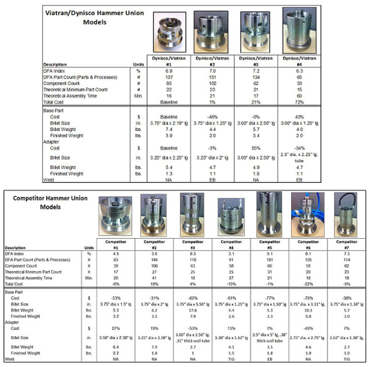
Figure 2: (Top) Benchmark results for Dynisco/Viatran Hammer Union products. Unit #1 serves as the baseline all other units are compared with. (Bottom) Benchmark results for Competitor Hammer Union products.
"The more parts there are in an assembly, the greater the difficulties or intricacies in the design and the lower the Index number," says Miles. "We saw competitors with both lower and higher Indexes when compared to our products. Based on that, we investigated what, in each design, led to a lower or higher Index. That was answered by what feature sets were included combined with how it was assembled. Using this information, we wanted to simplify as much as we could in the refreshed design to help our assemblers."
Following the DFA analysis stage of the benchmarking, Dynisco's VAVE Group undertook "should cost" analyses for all major machined components from each assembly using the Design for Manufacture (DFM) portion of the DFMA software. Major mechanical components were modeled in 3D CAD to recreate the assemblies and look at the amount of raw material used for the base part, and for the adapter, which houses the electrical connector for each unit. These were then analyzed with DFM to determine the cost to machine each part. Combining their DFM cost analyses with CAD models helped the team better understand material usage, the work-piece size (billet), the manufacturing processes used to machine the parts, and the final weight and cost.
The benchmarking results generated plenty of ideas for product redesign. "By ranking the attributes, we could use the information to avoid previously unknown pitfalls and to guide our new designs," says Joel Neri, engineering manager at Viatran. As subsequent rounds of design concepts were developed for the new hammer-union unit, now known as Model 511, the VAVE Group could provide both DFA and DFM analyses for each proposed assembly by quickly adjusting the DFA and DFM files created during the initial benchmarking process. Creating Pareto charts helped the team dive more deeply into the consequences of proposed design changes by identifying "Cost by Subassembly," "Part Count by Subassembly," and "Part Count by Type."
This highly collaborative effort generated a number of important design changes.
To improve access, the internal diameter of the adapter was increased to accommodate the protective gloves that many workers wear in the field. To protect the electrical connector from sledgehammer strikes (used by field workers to tighten the Weco nut down onto the hammer-union unit on the adapter top), the adapter wall was extended higher and thickened. To address debris collecting in the top of the adapter, the new model has four large window openings and a sloped surface around the connector, providing an easier path to flush out soil, dust, and mud.
And the most fundamental design change the team came up with adhered to the favorite saying of John Biagioni, Vice President/General Manager of Viatran, when talking about identifying waste in the business: "Eliminate the need." The 510 uses six screws to assemble the adapter to the bottom base part. Each screw uses a tear-drop, anti-rotation washer for durability in the heavily vibrating work environment, and each washer is secured with a retaining ring. That's a total of 18 fasteners to join two parts together.
"Reducing part count in product assemblies is a core tenet of DFMA," says Biagioni. "It consistently provides positive improvements in reliability, quality, and delivery and makes products cost effective and easier to assemble."
The clarifying design-thought the team came up with? Replace all 18 fasteners by making the adapter screw directly into the base part (Figure 3). Not only did this innovation eliminate screws, it also eliminated any perception from the field that the six visible mounting screws were a design weakness (they weren't, as will be shown later).
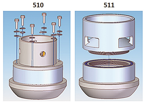
Figure 3: "Eliminating the need" for 18 fasteners on the model 510 (background) versus the new model 511 (foreground) in the assembly of the adapter to the base part.
During the redesign, the VAVE group also investigated different materials and manufacturing processes for the new model using DFM. Based on the design requirements and final geometry, the part was an ideal candidate for investment casting. By casting the adapter part to "near-net shape," time-consuming and costly machining processes could be completely eliminated.
For example, the second stage of the benchmarking exercise identified that the raw material workpiece used for machining the 510 adapter is a billet of 304 stainless steel that weighs 4.7 lb. After machining, the finished part ready for assembly weighs 1.1 lb -- which means that 3.6 lb of stainless steel, 76 percent of the billet, is being wasted. Switching to investment casting for the 511 adapter, a 2.9-lb casting blank is used and only 0.9 lb of material is machined away. Designing with the manufacturing process in mind resulted in significant reductions in both the amount of material used and processing time for the adapter.
DFMA metrics for the entire assembly tell the story well:
- An improvement in the baseline DFMA index from 7.0 for the 510 assembly to 9.6 for the 511.
- Total part count decreased from 102 for the model 510 to 66 for the model 511 (Figure 4).
- Two printed circuit boards were merged into one, and solder joints and a snap-fit electrical connector were eliminated.
- Overall, a total of 36 fasteners were eliminated.
- A 25 percent reduction in assembly time was projected.
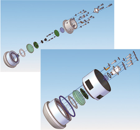
Figure 4: Part-count reduction: Model 510 (top) and 511 (foreground). Total part count decreased from 102 for the model 510 to 66 for the model 511.
With their design finalized for the 511, the team now needed to find out if the new model would fully meet its performance targets in the real world.
They started by creating rapid prototypes of the components' CAD files using stereolithography ("3D printing") technology. "This allowed us to touch and feel the parts and mentally walk through the asembly process while having them in hand," Miles says. The screw-down adapter was the design change that most dramatically reduced assembly time.
While physically manipulating their prototypes was helpful, the engineers also wanted to quantify the stresses and deformations that would affect the hammer union during actual use. So they developed finite element analysis (FEA) computer models from the 511 CAD files to simulate and predict the effects of both normal operating pressures and sledgehammer blows.
"Corrosion, vibration, and sledgehammer hits are the hammer union's enemies," says Miles. Baseline FEA analyses were run on the existing design as well as on the new one. "Similar to comparing our benchmarked design against the new one with DFMA analyses, we used the FEA analysis to ensure that the new design would meet, if not exceed, the performance and design criteria of the original," says Miles.
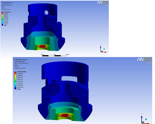
Figure 5: Finite element analysis (FEA) of pressure deformation in the 510 unit (top) versus the 511 (foreground) demonstrated that the redesigned 511 was as robust (or more) than the previous model.
"FEA can validate DFMA analysis by showing that you have a strong, robust, cost-effective design," says Miles. Adds Neri, "Using DFMA with 3D modeling and FEA really allowed design and development to progress more quickly before ever 'cutting metal.' This definitely saved a few expensive steps in the process."
FEA also showed that the screws in the 510 would NOT fail under typical impact loading in the field, (i.e., the adapter would deform first). As noted earlier, there had been a perception from the field that the screws were a weak point; of course eliminating them in the redesign completely removed that perception.
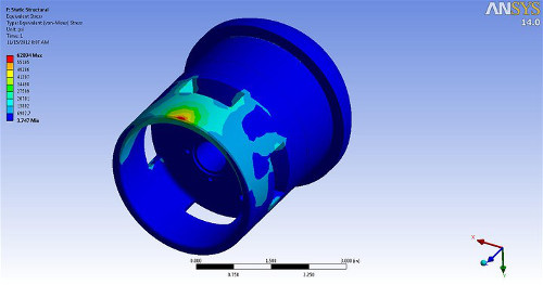
Figure 6: The redesigned 511 adapter also underwent FEA analysis of stresses from hammer strikes in the field, to prove out the integrity of the new configuration.
The far-reaching effects of Total Cost of Ownership
The early, combined focus of DFMA, Lean, and VAVE on the design of the 511 hammer union was complemented by a Total Cost of Ownership (TCO) initiative that Biagioni implemented at the same time. TCO analysis begins with the piece-part costs procured from within the supply chain as the TCO model considers where those are purchased -- factoring in freight, insurance, duties, and fuel surcharges in shipping from supplier to the business. Finally, additional overhead and risk factors are added into the calculation.
In the case of the 511 project, the team reviewed what TCO would be for a hammer-union piece-part procured from a supplier in China. They tracked its movement from Shanghai to Dynisco headquarters in Massachusetts, near their welding supplier. But then there was a switch in suppliers, and no adjustment to the value stream: The part next went to Viatran near Buffalo, NY. After inspection, the part was put in sets and shipped to a second welding supplier in Syracuse. Post-weld, the two-piece weldment was shipped to yet another supplier for clean-up and finally back to Viatran for assembly.
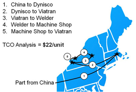
Figure 7: Value stream map for Dynisco part. Total Cost of Ownership (TCO) analysis revealed hidden overhead expenses that could be reduced with a "build where you sell" philosopy.
The TCO analysis of this exhaustive and expensive value stream (Figure 7) showed an additional $22 per hammer-union unit in overhead expenses. To correct this kind of situation, Dynisco has adopted a philosophy of regional manufacturing and distribution. "In its simplest form, this means build where you sell the product," says Biagioni. "Regional manufacturing and distribution is currently the quickest way to fulfill demand while minimizing risk."
Response to demand, wherever it may be, is also improved by incorporating Lean Postponement into designs to enable the quickest possible reaction to variation. This involves designing products using as many Commercial Off-The-Shelf (COTS) components as possible, parts that can be made anywhere in the world because they have been right-toleranced.
Postponement was worked into the 511 redesign as well. Since customers require many types of electrical connectors, the 510 hammer union offers seven different options. The same is offered on the 511, but now Viatran has just one casting blank part number into which they can machine the tapped mounting holes and bore for seven different connections. "The same goes for how we stock parts," says Miles. "We don't build up assemblies with the different adapters and connectors; we build them as we need them. These are the kind of downstream effects we see from using DFMA strategies. We had 10 drawings for the 510 adapter. For the 511 we only have two!"
With the 511 project nearing completion, the team anticipates running future projects in the same way. "That will be easy now, since we have fundamentally changed our product development process with DFMA, Lean, VAVE, and TCO," says Miles. "This 510 Hammer Union pressure transmitter project provided us with an opportunity to fully explore the power of all these tools and document the results. We followed our new process to a 'T' with the 511, and the results speak for themselves. We've learned to design faster -- and smarter as well."
Sidebar: The hammer-union pressure transmitter
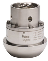
A signature product in the Viatran portfolio is the Hammer Union (HU) Pressure Transmitter 510, which is designed for use with a Hammer Union fitting in oil well installations. Among the salient features of the HU fitting:
- Model 510 forms the male sub of the Hammer Wing Union. It features an essentially flush-face pressure sensor so that mud and cement mixture cannot accumulate and interfere with the measurement.
- Three lug nuts and self-locking ACME threads provide fast make-up and breakout regardless of the position or space constraints and without special tools. The pressure fitting features a replaceable primary lip type seal ring in the female sub that protects the secondary metal-to-metal seal from abrasion and corrosion while minimizing flow turbulence.
- All parts of the HU wing fitting of the same figure number, size, and rating are interchangeable, so transmitters can be installed in any HU fitting.
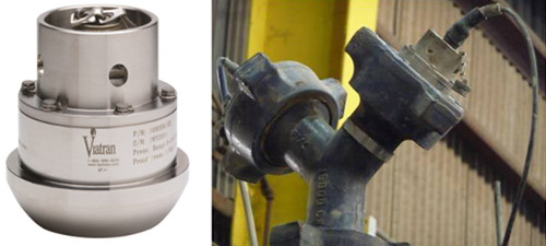
Figure 8: (Left) Viatran Hammer Union Model 510 and (right), a hammer-union unit installed.
Source: Boothroyd Dewhurst
Published May 2014
Rate this article
View our terms of use and privacy policy