 |
| December 09, 2014 | Volume 10 Issue 46 |
Designfax weekly eMagazine
Archives
Partners
Manufacturing Center
Product Spotlight
Modern Applications News
Metalworking Ideas For
Today's Job Shops
Tooling and Production
Strategies for large
metalworking plants
Engineer's Toolbox - Mobile Machines:
Options for driving hydraulic pumps
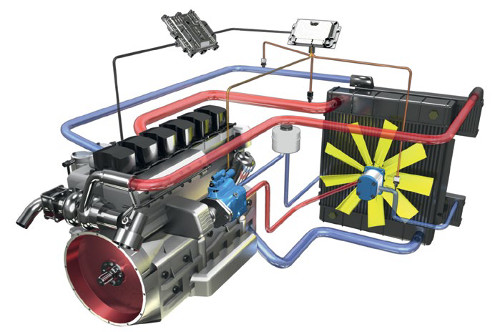
Electronically controlled hydrostatic fan drive systems reliably keep combustion engines at their optimum operating temperature, even under the most difficult of application conditions, enabling mobile vehicles to comply with strict emissions regulations for exhaust gas and noise.
Many of today's on- and off-highway applications utilize hydraulics as a way to provide working energy that is more compact and precise than traditional mechanical methods. There are many components that comprise these systems such as valves, cylinders, motors, and -- of course -- a hydraulic power source, the pump.
The prime purpose of the pump is to convert the input of mechanical, rotational power into hydraulic power, meaning flow for the required functions on the machine. Hydraulics are used for many different mobile machine functions such as systems for transit drives, swing functions, boom operation, conveyor drives, etc. In all of these functions, there must be a pump located somewhere in the system that provides the flow to accomplish the intended work. Where that pump is placed in the system is dependent upon the availability of a mechanical rotational power source to drive the input shaft of the pump.
There are two separate base-type applications, on- and off-highway, that provide opportunities and distinct ways for pump-mounting locations and drive inputs. Although there are a variety of options, keep in mind there is not one input that is preferred over another. Usually, the design envelope that the OEM engineer has to physically fit the pump within eliminates some options or maybe even all but one. However, it is important to understand the pros and cons of each type of input.
On-highway equipment
On-highway applications such as concrete mixer trucks, truck-mounted cranes, and dump beds rely on traditional mechanical transmissions to move the vehicle. For these vehicles, there are a few options for providing the rotational power for on-board hydraulic pumps. The hydraulic pump is generally mounted on the side of the vehicle's gearbox integrated power take-off units.
A power take-off (PTO) is any of several methods for taking power from a power source, such as a running engine, and transmitting it to an application, such as an attached implement. Most commonly, it is a system comprising of a splined output shaft designed so that a pump drive shaft can be easily connected and disconnected. The PTOs are engaged and disengaged by means of the truck's pneumatic system.
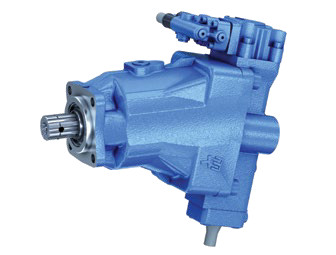
Figure 1. For on-highway applications, the hydraulic pump is generally mounted on the side of the vehicle's gearbox-integrated PTO with tight space parameters around the axle. Bent-axis pumps contain pistons mounted at an angle, offering a compact solution that still provides a wide range of displacement.
For these types of inputs, there is often little space between the PTO and the transmission axle; therefore, the size and shape of the pump must be considered. A large displacement pump may be too wide or long for using this input area (because of interference with the axle), so it is important to research the pump manufacturer's options for mounting requirements.
Bosch Rexroth offers pump mounting flange options that are compact in space or bent-axis pumps (Figure 1) that would offer better clearance around the axle. Bent-axis pumps are similar to bent-axis motors in that the piston pump contains pistons mounted at an angle to a drive shaft, which rotates the pistons. This angle, typically around 25 degrees, allows for a compact mounting area yet provides a wide range of displacement.
Auxiliary engines (in addition to the main vehicle engine) are often seen in truck-mounted applications when full engine horsepower and torque are required. Applications such as large vacuum pumps typically use this method. In these cases, there can be multiple pumps on a multi-pad gearbox that is directly driven by the auxiliary engine's output shaft. This type of configuration allows for multiple pumps, as well as potentially greater flexibility for pump size considerations. In this situation, it is important to make sure that there is adequate horsepower available to the hydraulic pump(s) for the intended performance of the function being controlled.
Off-highway equipment
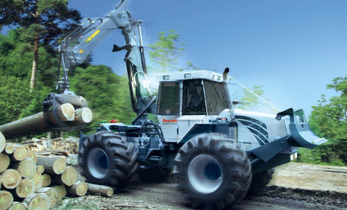
Off-highway equipment is typically designed for a specific machine purpose or activity and does not follow a pre-existing drive chassis, allowing for several available options to provide rotational power for pumps.
In comparing on- and off-highway equipment, it is best to understand the base design principles for each type of equipment. On-highway systems are usually based on an existing vehicle drive chassis. Off-highway equipment typically does not follow a pre-existing drive chassis and is designed for a specific machine purpose or activity. This allows the designers to work with a blank canvas for providing rotational power for pumps. Options that are typically used in these applications are: engine flywheel case coupling, engine crankshaft, belt/pulley, single or multi-pad PTOs, and pumps with built-in through-drives. Similar to on-highway applications, there is not one single method that is better than another, but there are design considerations for each method.
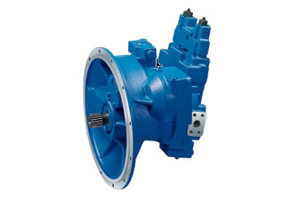
Figure 2. Usually found in machines that use the hydraulics system as their only means to perform work, like excavators and feller bunchers, engine flywheel mounts for pumps allow a direct coupling to the diesel engine and offer installation space savings for applications.
Some pump manufacturers offer engine flywheel mounts for their pumps that allow a direct coupling to the diesel engine. Most of these purposed pumps are in the high-pressure category, such as the Bosch Rexroth A11VO and A8VO (Figure 2), and offer installation space savings for applications. These are usually found in machines that use the hydraulics system as their only means to perform work, like excavators and feller bunchers. In these applications, the engine power does not have to drive an axle, mechanical transmission, or cardan shaft, allowing for space-saving installations.
There are many times when the pump must be located in a different area of the application due to space constraints around the engine and machine frame. In these instances, an engine crankshaft can be used to couple the pump to the mechanical drive of the engine. For this type of mounting/coupling, it is important to monitor the angle and balance of the connection method to the pump to avoid undesired bending forces of the pump shaft. The pump drive shaft must be parallel to the engine crank shaft. Otherwise, an oscillation will be introduced to the pump drive speed that can eventually destroy the pump. Consult the pump manufacturer for the amount of allowable bending and axial forces the pump is designed to accommodate or to find ways to avoid the impact to the pump.
Belt and pulley systems offer an alternative to PTO-driven methods. These are typically seen when access to the engine PTO is obstructed or when there is limited area around the engine. A design consideration for this type of input is the amount of horsepower that can be transmitted to the pump via the mechanical belt drive as well as monitoring the bending moments with axial and radial loads on the input shaft. These conditions usually limit the maximum possible power transmission and therefore pump size.
As discussed earlier, the limited space available for a standard engine single PTO can cause installation problems for hydraulic pumps. Depending on the desired displacement of the pump, the installation space claim for the pump may prevent an easy mounting to the engine PTO. The result is that the manufacturer may need to utilize spacers or other costly add-ons to allow for larger displacement pumps to be mounted. Consult your pump supplier to see if they offer any space-saving options for these situations that may allow for larger displacements to be used in tight areas.
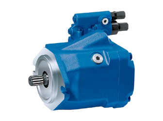
Figure 3. Limited space available for a standard engine single PTO can cause installation problems for hydraulic pumps. A solution is to use a pump that allows for larger displacements to be used in tight areas or employ two smaller pumps in a tandem/through-drive package.
The Bosch Rexroth medium-pressure open loop pump A10VNO (Figure 3) offers a solution in these types of situations where a compact unit with high displacement is needed for small installation spaces. Another idea sometimes utilized is to employ two smaller pumps in a tandem/through-drive package, which when built up together are smaller in diameter, but become significantly longer.
Multi-pad PTOs offer the largest amount of flexibility for applications requiring multiple pumps. If you have multiple pumps that will need to operate at different input speeds, a multi-pad PTO typically can offer different output speeds by changing the internal gear ratios for each pad.
Driving multiple pump stack(s) in a system can also be accomplished by utilizing pump through-drives. Most axial piston pumps offer a through-drive option to allow for mating an additional pump to the back. These through-drives are available in various sizes to allow for different mounting flanges such as SAE, A, B, C, or other standards. Many combinations can be created by this method, but one must consider the available maximum torque levels each pump or through-drive can provide to the additional mounted pump. There are also maximum limitations in regards to bending moments/weights/lengths of the pump stack (rear support of the stack(s) may be necessary) and a limitation of the torque available at each pad.
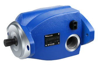
Figure 4. Energy-efficient fan drives like the compact A1VO provide opportunity to switch to a variable fan drive system which uses hydraulic power on as it is needed.
Other considerations
Even with the cases mentioned, there are still other elements of the machine design that should be considered for determining the input method to the hydraulic pump. The impact of Tier IV final emissions on machine design should be considered. The additional engine exhaust after-treatment systems will take up more real estate on mobile equipment. This will present new challenges for hydraulic systems as more pumps with higher power density will be required due to space limitations. These power-dense pumps may be operating at higher pressures that may alter how the pump should be driven within the system.
Additionally, it is now well known that the upcoming Tier IV final engines show a more demanding torque/load ripple effect due to the higher injection pressures. As pumps are used on direct engine drives as well as PTOs, it is important to consider the amount of angular acceleration (rad/s2) fluctuation of the driven pump input. Most pump manufacturers have published limits of angular acceleration that the input shaft can withstand.
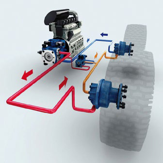
Hydraulics are used for many different mobile machine functions, all of which require a pump that provides the flow to accomplish the intended work. There are many options for where that pump is located, dependent upon the availability of a mechanical rotational power source to drive the input shaft of the pump.
In summary, manufacturers of both on- and off-Highway equipment must consider the desired functionality of the machine while evaluating the best approach to transfer the engine power to the desired function. The pump drive is a key decision in the layout of the machine and overall performance for the OEM. Depending on where the hydraulic work is performed, e.g. at the cylinders on a boom or the wheel drives of a loader, the freedom that hydraulics provides allows the designer to place his components in multiple locations on a machine that cannot be surpassed by any mechanical drive. Pumps can be placed with complete disregard to the point of power usage. This is one of the major reasons designers of mobile machinery will continue to use hydraulics for years to come.
Source: Rexroth
Published December 2014
Rate this article
View our terms of use and privacy policy
