 |
| May 07, 2019 | Volume 15 Issue 17 |
Designfax weekly eMagazine

Archives
Partners
Manufacturing Center
Product Spotlight
Modern Applications News
Metalworking Ideas For
Today's Job Shops
Tooling and Production
Strategies for large
metalworking plants
Engineer's Toolbox:
Driving automotive plastics design and manufacturing forward with computer tomography (CT) visualization and analysis software
By Kamil David Szepanski, Technical Solutions Expert, Volume Graphics
Plastics has been an ideal material for high-volume, durable products for decades. For the automotive industry, plastic molded parts range from instrumentation buttons, intake manifolds, and cooling and heating vent components, to aerodynamic exterior sections of sports cars, trucks, and SUVs. These broad part categories may involve advanced carbon and glass fiber-reinforced plastics (CFRP and GFP) alongside standard go-to plastics such as PA 6.6 or ABS.
With 50 percent of today's vehicles comprised of plastics -- a figure forecast to grow to 75 percent by 2020 -- the need to better manage design challenges, production efficiency, and quality in a uniform digital environment has never been greater.
One way of meeting competitive design, production, and quality challenges in automotive plastics is by fully integrating part inspection and analysis with computer tomography (CT) scanning systems. While CT is not a new approach in and of itself, the software that interprets CT data has made significant strides recently in accurately comparing manufactured parts against original CAD data and providing rich insights into issues of geometry compliance, tolerancing, porosity, mold design, and fiber orientation. Such improved capabilities significantly enhance the economics of molding via direct costs (yields, speeds, labor), along with lowering warranty and service expenses for OEM manufacturers and their supply chains alike.
Automotive lightens up and stands out
The automotive industry is at the forefront of lightweighting among high-volume commercial products. In the quest for lighter and stronger plastic parts, the industry is experimenting with adding porosity and fiber and producing innovative shapes that expand functionality and performance. With these new efforts come deeper challenges that add to the familiar, problematic factors of predicting shrink rates, flow, and cooling -- and then verifying final part dimensions.
Today, whatever can be done correctively to anticipate production outcomes -- up front in design and by actively informing design -- should be embraced!
With both quality and future digital automation in mind, new inroads in CT analysis software are helping speed up and optimize part and mold design. Not only can it conduct high-fidelity structural analyses on parts, it is already being used to guide geometry correction for molds and tool cutting, and also to improve production settings. Longer term, advanced scan analysis can be used for examining parts in the field to learn how components endure and change in their service environments. Deep, accurate, digital CT results files preserve the past and inform the future.
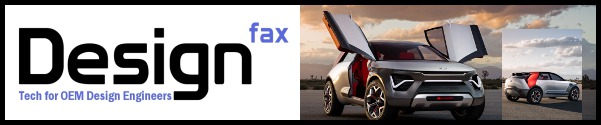
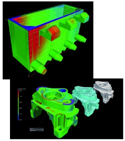
Geometry correction: Working on CT-scan data, manufacturing geometry correction software provides color-coded visualization of any deviations of the manufactured part from the master model. The output CAD elements can then be used to correct tools for injection molding and casting, or geometries for 3D printing.
After manufacturing, comparing actual part dimensions and tolerances to the original CAD model is the first priority for engineers. Integrated computer-aided mold and part design is a very mature science today. However, there is still a black art involved in pushing design boundaries for unusual shapes and meeting other demanding performance and cost goals. Assigning tolerances to specific material choices requires a superior understanding of behaviors in the molding process and in the potentially harsh environments that products face once released. Advanced CT software addresses the most challenging, impossible-to-access surfaces (internal as well) and captures tolerances while checking mating specifications for assemblies and part interfaces.
In the process of making test parts and tooling (soft and hard), the software provides critical feedback on a range of deviations from wall thicknesses to warpage and more. Engineering teams that include both designers and toolmakers can then conclusively determine if it is the design or the mold that may need rework. It is easy to over-debate and iterate this stage without the benefit of hard data and the excellent visualization tools now available through third-party CT analysis software.
New developments
Accuracy, user friendliness and visualization are key to the new generation of CT evaluation software. Again, checking actual surfaces and features against nominal values is critical and fundamental to inspection of plastic parts. This one activity is often enough for parts manufacturers to know that they have met customer requirements. Furthermore, advanced approaches make nominal/actual comparisons simple for first-article inspection and much faster in follow-on repeat scans of individual production runs and batches -- confirming constant production and quality within the shortest time.
Essentially, the scanned data is imported into the analysis software and compared to the master CAD model in an overlay fashion that highlights the nominal range of accepted tolerances, deviations, and faults against the real-world geometry. Graphical color plots make these digital comparisons and call-outs instantly noticeable to the eye. From there, teams -- be they designers, molders, or quality professionals -- can consider corrective actions to the model or mold in order to meet the desired specification. And these changes are not made on assumptions and black art, but definitive data. Now the team can deploy manufacturing correction technology that automatically adjusts geometry in either the mold or CAD model to achieve the desired outcome. This function works the same for additive manufacturing, too.
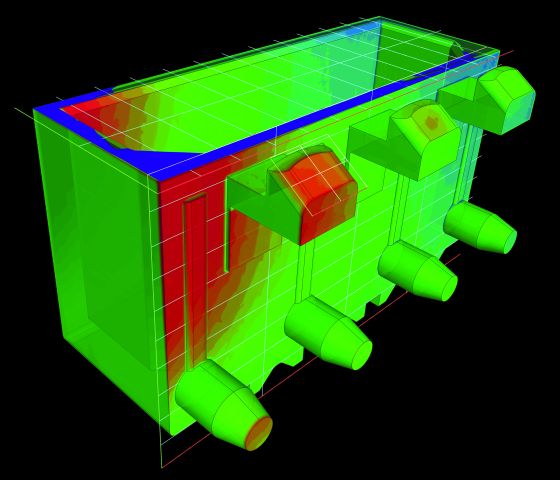
Nominal/actual comparison: A CT-scanned object compared with its respective CAD data set. Color-coded analysis results and local annotations show deviations. The software allows for geometric comparison of voxel, mesh, and CAD data.
The beauty of the whole process is that high-fidelity analysis software reveals geometric complexity much more accurately than tactile measurement approaches. Designs can also be digitally divided into prioritized areas of interest (segmentation), thereby saving valuable analysis time. Destructive testing is unnecessary: The software reveals porosity, external and internal, as well as otherwise impossible-to-access hidden areas of concern such as passageways, weld zones, cracks, voids, sinks, and density changes -- no matter where. The ability of today's CT analysis software to provide high-definition, granular analysis is quite stunning!
Without delving into all the performance areas, this advanced software automates a substantial amount of the interaction previously required between inspection and CAD geometry, CAD Product Manufacturing Information (PMI), simulation, and manufacturing (molding, casting, cutting, and additive manufacturing).
Looking now, looking ahead
Beyond proving quality in finished plastic parts, high-fidelity CT analysis can support advanced lightweighting techniques in porosity-induced plastic designs, evaluate fiber strategies used for strength, and encourage creation of innovative geometries that improve automotive ventilation, aerodynamics, aesthetics, and more.
The latest software is already being used extensively in the European automotive market where the cost-to-benefit relationship has been clearly met. Other vehicle markets will benefit, too, by embracing new methods that contribute to customer satisfaction and help business sustainability. Automation and Industry 4.0 are on the horizon and closing in. Advanced CT analysis software for inspection and concurrent design and process improvement can be an important contributor to the all-digital vision of tomorrow's factories.
About the author
Kamil David Szepanski is technical solutions expert at Volume Graphics. He can be reached at
support-us@volumegraphics.com. Phone: 704-248-7736 Ext. 103.
Published May 2019
Rate this article
View our terms of use and privacy policy