 |
| November 26, 2019 | Volume 15 Issue 45 |
Designfax weekly eMagazine

Archives
Partners
Manufacturing Center
Product Spotlight
Modern Applications News
Metalworking Ideas For
Today's Job Shops
Tooling and Production
Strategies for large
metalworking plants
Engineer's Toolbox:
Three steps to mount a step motor
By Jeff Kordik, Chief Technical Officer, Applied Motion Products
Regardless of motor size, operators should follow these three basic steps to mount a step motor:
- Use the pilot to center the motor to the load (see item 1 in Image 2). The pilot on the motor face is concentric with the motor shaft. Using it when machining the mounting surface for the motor enables alignment of the load with the motor shaft.
- Mount the motor securely against a surface with good thermal conductivity such as aluminum. Because all motors generate heat, providing a path for heat generated by the motor to dissipate into the mounting surface allows the motor to run cooler. If the heat in the mounting surface or machine frame is undesirable, another option is to cool the motor with a fan. A good rule of thumb is to keep the motor surface temperature below 90° C. If the motor gets too hot, the insulation on the internal motor windings will melt, resulting in a short-circuit and having to scrap the motor.
- Properly align the motor with the load using a flexible coupling. Installed between the motor shaft and load, a flexible coupling helps compensate for minor misalignments made during the motor mounting. Helical couplings are a good example of flexible couplings that handle angular and lateral misalignment.
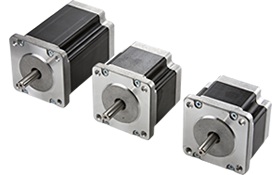
Pro tip: Use an off-the-shelf bracket to mount the motor. Instead of machining a mounting bracket from scratch, purchase pre-fabricated brackets that offer convenience and repeatability from unit to unit. Mounting brackets are available in standard sizes such as NEMA 17, 23, and 34. Since step motors generate heat, aluminum mounting brackets are preferable to steel.
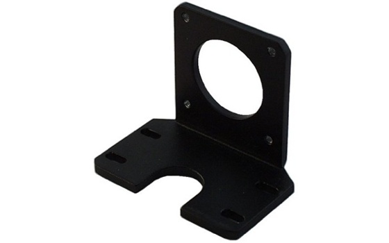
Image 1. An off-the-shelf mounting bracket that includes the properly dimensioned pilot hole and four tapped mounting holes for #8-32 screws.
Key mounting dimensions
The following motor outline (Image 2) highlights the key mounting dimensions of the step motor:
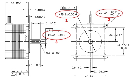
Image 2. Key mounting dimensions of a NEMA 23 step motor are numbered.
- Item 1: Pilot diameter. Make a precise hole in the mounting bracket that matches the pilot of the step motor and is concentric to whatever you'll connect to the motor shaft.
- Item 2: The bolt hole diameter determines the maximum screw diameter that you can use to mount the motor. Size NEMA 23 and larger motors have four thru-holes. Smaller motors, NEMA 17 and below, have two or four threaded blind holes or studs.
- Item 3: Motor shaft diameter determines the correct coupling to use.
Pro tip: To protect a motor from shock loads, avoid driving the load into a hard stop (i.e., metal on metal contact). Overhanging loads result from cantilevering a mass off the end of the shaft. Thrust loads are loads that pull on or press into the motor shaft, such as a vertical load or a large mass connected to a screw or belt that moves linearly. To avoid breaking the shaft or reducing bearing life, consult this guideline: https://www.applied-motion.com/sites/default/files/Stepper%20Motor%20Life%20data-110817.pdf.
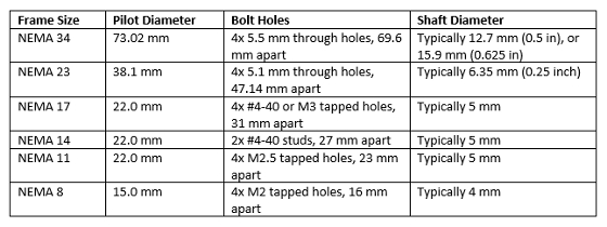
Mounting dimensions by NEMA frame size
The following are mounting dimensions for common NEMA step motor sizes. Consult drawings from the motor manufacturer for additional details, including tolerances:
Disclaimer: Follow all applicable local and national codes that regulate equipment installation. As codes vary from area to area, it is your responsibility to determine which codes to follow and to verify that the equipment, installation, and operation comply with the latest revision of these codes. Equipment damage or serious injury to personnel can result from the failure to follow all applicable codes and standards.
SIDEBAR: Tips for determining proper step motor torque
When specifying a step motor for a motion control application, operators must determine the torque necessary to accurately position load. The process of "sizing an application" involves calculating the required torque and speed range necessary to move the load. For example, if needing 80 oz-in. of torque at speeds up to 10 revolutions/second (rps), an operator could use the step motor and drive shown in Chart 1 along with a 24-V DC power supply.
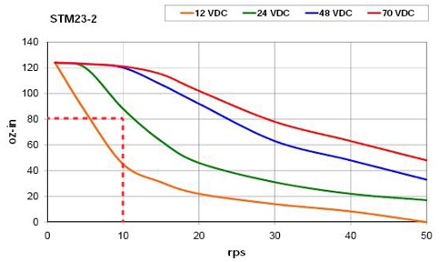
Chart 1: Speed-torque curves illustrate the torque achievable with a given step motor and drive at a variety of commonly available power supply voltages. The dashed red line indicates a theoretically required torque of 80 oz-in. at 10 rps.
If the motor needed to provide a torque of 80 oz-in. at a faster speed of 20 rps, the same motor and drive could be used if the power supply voltage were increased to 48 V as shown in Chart 2.
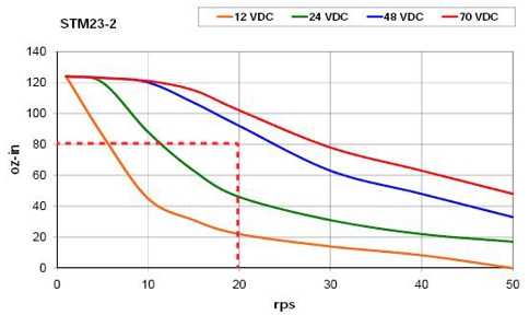
Chart 2: The dashed red line indicates a theoretically required torque of 80 oz-in. at 20 rps.
Always choose step motors based on published speed-torque curves, and include a margin of safety. For open-loop operation, size the motor with a 30 to 50 percent torque margin at a speed that ensures the step motor continues to turn and provides enough torque to move the load. A simple way to do this is by imagining a line parallel to the speed-torque curve at roughly 1/2 to 2/3 the height of the published curve.
For additional functionality, add an encoder to the step motor and drive system. The encoder serves as a feedback device to ensure the correct motor position and notifies the system if the motor does not have enough torque to move the load.
Learn more at www.applied-motion.com.
Published November 2019
Rate this article
View our terms of use and privacy policy