 |
| December 07, 2021 | Volume 17 Issue 45 |
Designfax weekly eMagazine

Archives
Partners
Manufacturing Center
Product Spotlight
Modern Applications News
Metalworking Ideas For
Today's Job Shops
Tooling and Production
Strategies for large
metalworking plants
Engineer's Toolbox:
How to select the proper pin for your application
By Jeff Greenwood, Product Sales Engineer, SPIROL International Corporation
Fasteners are some of the most important parts of an assembly, as they hold the entire assembly together and facilitate the interaction between the individual components. Ideally, the selected fasteners are simple to assemble, provide a quality product for the intended lifetime of the assembly, and yield the overall lowest cost of the assembly taking into account the entire manufacturing process. This article focuses on how to select the proper pin for an application. Specifically, press fit pins are discussed here, as they are the most common type of pins used in modern manufacturing.
PRESS FIT PIN TYPES
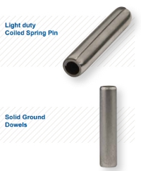
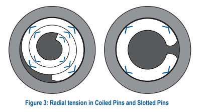
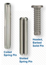 Among press fit pins, there are two general categories: Solid Pins and Spring Pins. Solid Pins can have a smooth, uninterrupted surface (such as dowels) or they may be designed with retention features such as knurls and barbs. All Solid Pins are retained by displacing/deforming the host material. Conversely, Spring Pins retain themselves by exerting a radial force (tension) against the hole wall after installation.
There are two different types of Spring Pins: Slotted Pins and Coiled Pins. Slotted Spring Pins are general-purpose, low-cost pins typically recommended for noncritical assemblies. Oftentimes, Slotted Pins are used in applications where they are manually installed into mild to hardened steel components. Slotted Pins have a gap designed for the pin to flex during installation, allowing the pin to absorb varying hole tolerance. Coiled Spring Pins are available in light, standard, and heavy duty to enable the designer to choose the optimum combination of strength, flexibility, and diameter suited for varying host materials and performance requirements. Coiled Pins have 2 1/4 coils of material that enable the pin to flex both during installation to accommodate varying hole tolerance and after installation to dampen shock and vibration to prevent hole damage.
APPLICATION EVALUATION
The first step in selecting a pin is evaluating the application. These are some of the many considerations when determining the proper pin for a specific application:
- What is the pin's function?
- What are the strength requirements of the pin?
- What is the material of the component in which the pin will be used?
- What environment will the pin be exposed to?
- What is the intended product lifetime and number of cycles?
- How will the pin be installed?
- What is the expected volume?
Designers should thoroughly examine the application and performance requirements early in the design stage. Not only will this guide facilitate decisions about the design of the host component(s), but it will also cover the topics of fastener selection, fastener size, material, duty, etc. Unfortunately, many designers wait until the end of the design to select a fastener. This can constrict the fastener selection process, limit performance, and force suppliers to use high-cost manufacturing processes to meet overly complicated specifications. It is recommended that manufacturers consult with pinning technical experts during the early stages of a new design so that the proper pin is selected and the appropriate specifications are applied to the mating components for the application.
COMMON PIN FUNCTIONS
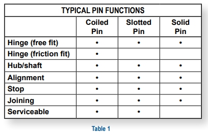
While there are many different ways to use pins, the most common are shown in Table 1. These guidelines apply the majority of the time, but each specific application should be evaluated for final determination of which pin type is most appropriate.
Hinge
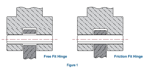
There are two primary types of hinges:
- A free fit hinge has little to no friction or drag when the latch or handle is rotated. Hinge components are "free" to rotate independent of one another.
- A friction fit hinge requires interference to prevent free rotation of components relative to one another. Depending on design intent, resistance can vary from a slight drag to a value sufficient to maintain the fixed position of components anywhere in their full range of rotation.
All types of press fit pins should be considered when designing a free fit hinge. Solid Pins are often preferred when the pin must travel through multiple clearance holes or when there is limited engagement area in the host component. Coiled Pins are preferred when there is no axial load on the pin and for applications with shock and vibration. Slotted Pins are preferred when cost is paramount (typically at the expense of quality) and performance is sufficient. In general, Coiled Pins are preferred for friction fit hinges because they provide uniform radial tension that creates a "resistance" feel in the hinge. Additionally, Coiled Pins are far more flexible than Slotted Pins or Solid Pins, thereby reducing the risk of damage to the holes during installation and normal product usage.
Hub and Shaft
One of the primary benefits of using a Coiled Pin to affix a collar or hub to a shaft is the Coiled Pin's ability to prevent hole damage. The Coiled Pin's flexibility and ability to effectively absorb forces make it the ideal pin for most hub and shaft applications.
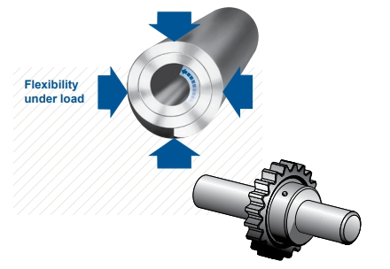
While all three types of pins can be used to affix a hub/gear to a shaft, the Coiled Pin provides superior performance and extends the lifetime of the assembly compared to the other pins.
Locating/Alignment
 The desired level of precision dictates which pin is appropriate. Coiled Pins are preferred for the vast majority of alignment applications because they conform to the holes in which they are installed and remain flexible. Therefore, maximum accuracy in alignment can be achieved with a "light" press to seat mating components. Light-duty Coiled Pins are especially advantageous for low insertion forces. Wider hole tolerances can be used with Coiled Pins, which reduces the total manufacturing cost of the product. However, the more precision required, the tighter the hole tolerances need to be controlled in each component and in relation to each other.
Ground Dowels are preferred for highly critical alignment applications. Unlike Spring Pins, Solid Dowels rely on material displacement between the pin and the host components for the press fit. This requires a considerably higher installation force than either Spring Pin and requires that the holes be precision machined, which increases cycle time and manufacturing costs.
Stop
Coiled Pins, Slotted Pins, and Solid Pins are all commonly used to stop the movement of one component relative to another. For example, Coiled Pins are often used to prevent over-rotation of an actuator.
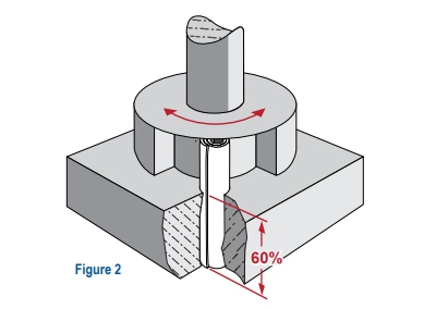
When Slotted Pins are used for this purpose, it is recommended that the pin's slot is oriented opposite from the component interacting with the pin. Conversely, Coiled Pins and Solid Pins do not need to be oriented. Additionally, when Spring Pins are used as a stop pin, at least 60% of the pin's length must be retained in the static component to ensure retention as shown in Figure 2.
Joining/Retention
Coiled Pins, Slotted Pins, and Solid Pins are also commonly used to join components together. Coiled Pins and Slotted Pins hold components together with the frictional force generated from the radial tension of the pin. Coiled Pins and Slotted Pins are serviceable in the same hole.
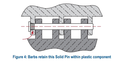
Solid Pins provide superior retention when an axial load is applied and are not removable/serviceable. This is advantageous when designers do not want users to disassemble their product. For the vast majority of retention applications, external features like knurls or barbs are preferred over ground solid dowels because they often provide cost savings.
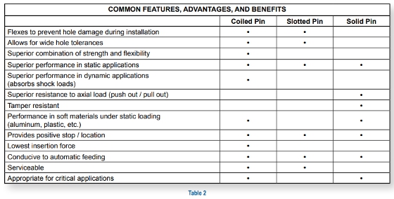
FEATURES, ADVANTAGES, BENEFITS
Each type of press fit pin serves a purpose for manufacturers. Table 2 compares the common features, advantages, and benefits for each type of pin.
GENERAL CONSIDERATIONS FOR PIN SELECTION
Spring Pins are typically preferred over Solid Pins because of their flexibility, lower insertion forces, and their ability to accommodate wider hole tolerances. Here are several common exceptions where Solid Pins are preferred:
- When a head is required for a positive stop or to retain a thin member to a thicker member of the assembly.
- When a smooth, uninterrupted surface is required such as when used in conjunction with a pawl or other angular component.
- When a hollow pin is not suitable such as when the designer is looking to plug a hole (i.e., restrict passage of liquids).
- When there is a need to manually align several clearance holes.
- When increased bending or shear strength is required.
- When precise hole locations need to be maintained.
Coiled Spring Pins are undoubtedly superior when it comes to assemblies subject to dynamic loading. Coiled Spring Pins have a unique combination of strength and flexibility that allows them to dampen forces and vibration that prevent hole damage and prolongs assembly life.
While Slotted Spring Pins are used in similar applications as Coiled Spring Pins, Slotted Pins are typically preferred in non-critical, static applications where cost is prioritized over product lifetime.
REEVALUATE PRODUCT DESIGN
The final step in selecting the proper pin is to reevaluate the overall product design. Oftentimes, the pin evaluation process identifies new information about the assembly. Many manufacturers see significant benefits when they stay flexible with their product design while the fastener is finalized. Here are some actual examples of design changes that were implemented after the fastener evaluation process that lead to performance improvements, cost savings, and/or improved quality:
- New host material
Example: A manufacturer changed the material of their plastic housing from polybutylene terephthalate (PBT) to polycarbonate (PC) after seeing improved retention when using barbed Solid Pins. - Hole size
Example: A company increased the hole size in their hub and shaft from 2.95 ±0.05mm to 3.05 ±0.05mm so they could utilize a standard off-the-shelf Coiled Spring Pin. - Hole tolerance
Example: A company was able to eliminate a timely honing operation by using a Coiled Pin for alignment rather than a Ground Solid Dowel. - Boss thickness
Example: A plastic molder witnessed cracking during prototype testing of a plastic hinge. They implemented SPIROL's recommendation to increase the boss diameter surrounding the Solid Pin from 1mm to 3mm, which eliminated the cracking problem. - Hinge design change
Example: A plastic molder originally designed a friction fit hinge but was unable to achieve the high swing torque requirement over time with a Solid Pin, as the plastic would relax causing the hole diameter to open up. As a result, the swing torque would diminish due to the enlarged hole size. They replaced the Solid Pin with a Coiled Spring Pin and incorporated the associated design changes to the holes to meet the desired swing torque. The redesign resulted in the swing torque being maintained beyond the expected life of the assembly.
TESTING
It is prudent for manufacturers to perform testing with the fastener(s) that they have specified for the application to determine that the assembly performs as desired in the most extreme conditions. After testing is completed, engineers can compare measured test results with the performance requirements that were established. Ultimately, the proper pin for the application should satisfy the quality, performance, assembly, and cost goals of the manufacturer.
CONCLUSION
Designers can optimize the performance and total manufactured cost of a product by selecting the proper pin for their product. In order to do this, it's critical that fastener options are considered early in the design stages. The most important step in selecting the proper pin is to evaluate the application in detail and establish performance requirements. Finally, the design team should test and validate the fastener(s) in prototype assemblies before final approval is given.
See all that SPIROL has to offer at spirol.com.
View this article as a downloadable PDF at https://www.spirol.com/library/whitepapers/cldp-How_to_Select_the_Proper_Pin_for_Your_Application_us.pdf?sm=217151.
Published December 2021
Rate this article
View our terms of use and privacy policy