 |
| July 12, 2022 | Volume 18 Issue 26 |
Designfax weekly eMagazine

Archives
Partners
Manufacturing Center
Product Spotlight
Modern Applications News
Metalworking Ideas For
Today's Job Shops
Tooling and Production
Strategies for large
metalworking plants
Engineer's Toolbox: How to pin a shaft and hub assembly properly
By Christie L. Jones, Market Development Manager, SPIROL
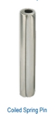 One of the primary benefits of using a Coiled Spring Pin to affix a hub or gear to a shaft is the Coiled Pin's ability to prevent hole damage. Another benefit is that the Coiled Pin absorbs wider hole tolerances than any other press-fit pin. This translates to lower total manufacturing costs of the assembly.
There are a few design guidelines that must be adhered to in order to achieve the maximum strength of the pinned system and prevent damage to the assembly.
The design guidelines can be divided into two groups:
1. The shaft and hub, and
2. The pin.
1. Shaft and Hub Considerations
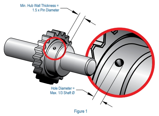
- The hole in a shaft should not exceed 1/3 of the shaft diameter. For mild steel and nonferrous shafts, standard duty pins are recommended. The extra strength of a heavy duty pin is only beneficial if the hole is less than 1/4 the diameter of the shaft or if the shaft is hardened (Figure 1).
- It is recommended that the hub be designed with a minimum wall thickness of 1.5 times the diameter of the pin. Otherwise, the strength of the hub will not match the shear strength of the pin (Figure 1). As the wall thickness of the hub increases, so does the area of material around the pin.
- The diameter of the holes through both the shaft and hub should be precision matched to eliminate any movement of the pin within the holes. It is recommended that the difference between the hole diameters in the hub and shaft not exceed 0.05mm (.002") to prevent movement of the parts relative to each other. Otherwise, the pin will be subject to dynamic loading such that a very small change in velocity could equate to a significant change in force impacting the assembly.
- The hole should be centered in both the shaft and hub to prevent stress concentration and ensure there is enough material around the pin to withstand the applied forces.
- If the holes cannot be precision matched, dividing the tolerance between the shaft and hub is recommended. The larger half of the tolerance should be applied to the component with the longest engagement length, and the smaller half should be applied to the other component.
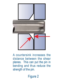
- Countersinks on the holes are not recommended. In addition, the outer diameter of the shaft (OD) and the inner diameter of the collar (ID) should be designed such that the distance between the shear planes (OD-ID) does not exceed 0.13mm (.005"). In both cases, an unsupported length of pin in an area where torque may be applied is created. This could cause a bending moment, which shortens the lifespan of the pin (Figure 2).
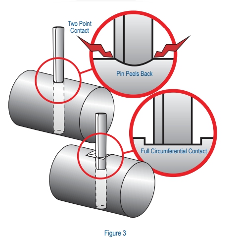
- Installing a cylindrical pin into a hole on the surface of a cylindrical object leads to two-point contact between the pin and the hole. This concentrates the compression force on only two points of the circumference. To increase the contact surface between the periphery of the hole and pin, and to ease installation, a flat should be placed on the exterior surface of the hole (Figure 3).
2. Coiled Pin Considerations
It is important to start with the load to which the pin will be subjected, and then evaluate the material of the host to determine the duty of the Coiled Pin.
The pin diameter needed to transmit the load in the proper duty can then be determined from the shear strength tables located in the SPIROL® Coiled Spring Pins design guide/product catalog, taking into consideration these further guidelines:
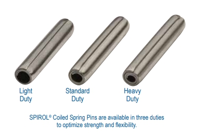
- Wherever space permits, use standard duty pins. Standard duty Coiled Pins have the optimum combination of strength and flexibility for use in nonferrous and mild steel components. They are also recommended for use in hardened components, as they have greater shock-absorbing capabilities.
- Heavy duty pins should only be used in hardened materials where space or design limitations rule out a larger diameter standard duty Coiled Pin. An exception to this rule is that austenitic (nickel) stainless steel pins should never be used in hardened components.
- A light duty pin is recommended for soft, brittle, or thin materials or where holes are close to an edge. In situations not subject to significant loads, light duty pins are often used because of the lower insertion forces required.
SPIROL Application Engineers can review your application needs and work with you to recommend the optimum solution. One way to start the process is to visit SPIROL's Optimal Application Engineering portal.
Although this article offers general design guidelines, it is recommended that Application Engineers who specialize in fastening and joining be consulted to ensure the optimum design is employed for each application.
Download this article and read other informative SPIROL engineering tips and white papers at spirol.com/resources/white-papers/.
Published July 2022
Rate this article
View our terms of use and privacy policy