 |
| October 11, 2022 | Volume 18 Issue 38 |
Designfax weekly eMagazine

Archives
Partners
Manufacturing Center
Product Spotlight
Modern Applications News
Metalworking Ideas For
Today's Job Shops
Tooling and Production
Strategies for large
metalworking plants
Top Tech Tips: How to specify electric rod-style actuators for optimal performance, reliability, and efficiency
By Andy Zaske, Vice President, Tolomatic
With today's demand for controlling costs while achieving high speed and high precision in factory automation, it is more important than ever to fully analyze a linear actuator application and precisely determine a project's parameters. This is especially true with electric rod-style actuators due to their higher initial cost, more advanced design, and more predictable performance compared to fluid power cylinders, both pneumatic and hydraulic. Additional engineering and analysis at the front end of an electric actuator application will reduce overall costs and result in automation systems with higher reliability, better performance, lower energy expenditures, and reduced maintenance.
In the hurry to get factory automation applications up and running, there is always the impulse to make educated guesses or take shortcuts. This paper will outline the Top 10 Tips to consider during sizing to ensure optimal performance, reliability, and efficiency of your electric rod-style actuator application.
Tip 1: Calculate loads precisely
The ability of an electric rod-style actuator to perform its intended task with accuracy, speed, and reliability is dependent on matching the electric motor, the lead screw, and the bearings to the anticipated loads. By knowing the precise static and dynamic loads of the application and matching them to the peak and continuous load capabilities of the actuator, the application will be both cost effective and reliable.
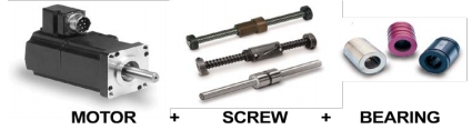
Motor, screw, and bearing selection must match the anticipated load capacity of the actuator for best performance and reliability.
Tip 2: Calculate for electric, not fluid power (pneumatic or hydraulic)
Oversizing actuators is a bad habit left over from fluid power applications where oversizing was considered inexpensive insurance against not having enough power. With fluid power cylinders, the additional cost of a slightly larger cylinder than necessary was minor compared to the extra engineering time that might be involved in sizing it correctly. It was common for engineers to build a 2:1 safety factor into fluid power applications for a variety of reasons. These included erring on the conservative side to compensate for imprecise knowledge of the loads, fluctuations in available air pressure, and oversizing in anticipation of higher loads in the future due to production growth or application changes. Electric actuators can cost significantly more up front, so oversizing is a more costly mistake.
Avoid oversizing by properly matching the actuator to the application. Sizing programs, graphs, and formulas available from actuator manufacturers make this task easier and more accurate than in the past.
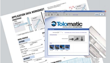
Tolomatic offers the "How To Guide: Converting Hydraulic Cylinders to an Electric Alternative." Application Data Worksheets and Windows-based sizing and selection software are also offered to simplify the sizing and selection process.
Tip 3: Factor in duty cycle
Duty cycle is defined as a ratio of operating time to idle time of an electric actuator expressed as a percentage. An actuator that is moving for two seconds and stopped for two seconds has a duty cycle of 50%.
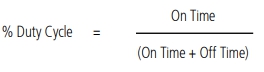
Duty cycle calculation.
Underestimating the impact of duty cycle on an actuator can lead to overheating, faster wear, and premature component failure. Overestimating the impact of duty cycle can lead to higher initial costs due to oversizing. Typical conservative duty-cycle estimates often stem from an incomplete understanding of the application.
Tip 4: Know required force and velocity
When considered together, force and velocity requirements dictate the capabilities of motors, screws, and nuts in electric rod-style actuators. A common error is specifying a stepper motor to save money when a servomotor may be more appropriate for velocity and force requirements. As the speed of a stepper motor increases, its available force drops off sharply, whereas servomotors are able to maintain their force even as speed increases. Similarly, force and velocity requirements will dictate the type and pitch of the lead screw -- whether it is an Acme screw with either composite or bronze nut, or a ball screw or roller screw. By knowing the precise speed and velocity requirements of the application, it is possible to specify an actuator with the proper components needed for high performance and long service life.
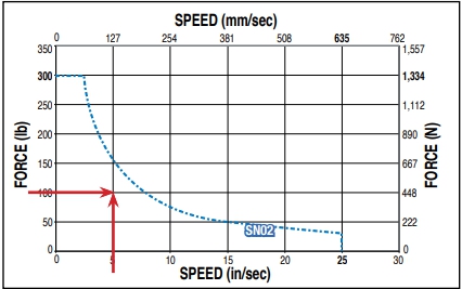
Use the screw charts supplied by the actuator manufacturer to determine if your force and speed requirements are compatible with actuator/screw capacities.
Tip 5: Employ proper guides and avoid side loading
A rod-style actuator is vulnerable to damage and wear if the extended rod is subjected to even moderate side loads. Side loads on the rod usually occur when the actuator is out of alignment with the main load, causing severe wear to the front bearing and damage to the lead nut. The mounting of the actuator can also be a factor. For example, an actuator rod will have a tendency to run out of alignment at maximum stroke when it is mounted with a clevis-type rod end, creating significant side loads on the rod and support bearing. To avoid side loading, be sure the actuator rod has an appropriate mounting and is either guided or precisely aligned with the load.
Tip 6: Set critical speed limits
Higher operating speeds can often improve manufacturing throughput, but in a rod-style actuator, lead screw critical speed becomes an upper limit. Critical speed refers to the rotational speed that excites the screw's natural frequency. When a screw reaches critical speed, it begins to oscillate or "whip." The critical speed limit is dependent on the screw length and diameter. As the stroke length increases, the distance between the support bearings increases, causing screw oscillation over a certain speed. This oscillation prematurely wears the support bearings and can result in vibration, noise, and even catastrophic failure.
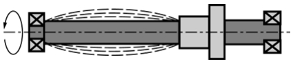
When the stroke of a rod-style actuator increases, so does the distance from the actuator's support bearing. In some cases, if the distance becomes greater than the capacity the screw and bearing can handle, oscillation of the screw occurs, placing stress on the bearings.
Tip 7: Match peak force to actuator
The peak force needed for the application cannot exceed the peak force that can be delivered by the actuator. First determine what the peak force requirement is for the application and then compare that to the force curve for the selected actuator. Force curves from actuator manufacturers show a combined peak and continuous force capability. For most of the duty cycle, the force stays under the continuous force curve. Make sure that the actuator's peak and continuous force capabilities are properly matched to the motor; some motors can provide more peak force than the actuator can withstand, causing stresses that will lead to premature failure.
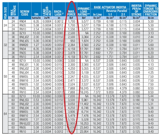
Be sure to use the manufacturer's tables or charts to determine the maximum force capacity of the actuator, and to select the actuator that best fits the application.
It is equally important to perform necessary column strength calculations and verify that the actuator is capable of providing the required peak force without screw or rod buckling.
Tip 8: Factor in environment
The environment in which the actuator will be operating can have a profound effect on performance, reliability, and maintenance. High temperatures can affect seals, lubrication, bearings, and motor life. Extremely low temperatures can also affect performance, lubrication, and wear. Contamination with oil, water, or abrasive grit can destroy seals unless the actuator has an appropriate IP rating. Since IP ratings only address static conditions, dynamic conditions (vibration, heat, cold, movement) also have to be considered.
Tip 9: Total envelope matters
It is important to consider the overall actuator "envelope" -- the length and width of the actuator and motor when the rod is fully extended. Failure to consider the total envelope may limit the size of motor that can be used or require an alteration in the layout of the application. Be aware that the overall stroke length and actual working stroke length of an actuator will be different due to the "dead length" needed to accommodate internal features such as lead nut, bumpers, and limiters.
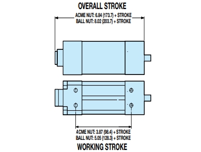
Overall stroke vs. working stroke.
Tip 10: Drive system is more than a footprint
The actuator may be specified with an inline or reverse-parallel (RP) motor mount/drive system. While a RP system offers a more compact length envelop, the RP system will cost a little more due to the additional machined components, belts, pulleys, or gears. RP motor mounts do offer gear/belt ratios for a mechanical advantage and inertia matching where an inline motor mount would require the addition of a planetary gearbox to offer these features in the actuator system. Additionally, the RP motor mount offers the mechanical mounting option of a rear clevis for applications requiring pivoting. From a performance perspective, the inline motor mount with a servo coupler offers slightly more efficient drive system and higher dynamic performance with the elimination of the additional components (belts, pulleys, gears).
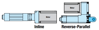
This illustration shows the space-saving feature of the reverse-parallel motor mounting option with a rear clevis as opposed to an inline configuration. Be sure to select the configuration that best suits the required performance.
Conclusion
Electric rod-style actuators offer enhanced performance, control, and efficiency over their fluid power (pneumatic and hydraulic) counterparts. However, because of the higher initial cost of electric actuators and their unique characteristics vs. a fluid power cylinder, it is essential to fully understand the application requirements. More productive and reliable automation systems will result from a careful determination and analysis of the loads, forces, application footprint, and environment.
----------------------
Interested in learning more? Visit the Tolomatic Information Center online for technical articles, case studies, white papers, a CAD library, sizing tools, and more. Since 1954, Tolomatic has been manufacturing innovative automation components -- from gearboxes and brakes to pneumatic actuators and complete electrical linear motion systems.
Published October 2022
Rate this article
View our terms of use and privacy policy