 |
| October 11, 2022 | Volume 18 Issue 38 |
Designfax weekly eMagazine
Archives
Partners
Manufacturing Center
Product Spotlight
Modern Applications News
Metalworking Ideas For
Today's Job Shops
Tooling and Production
Strategies for large
metalworking plants
Pro Tip: What is the clearance/thrust relationship in induction motors?
By H2W Technologies engineers
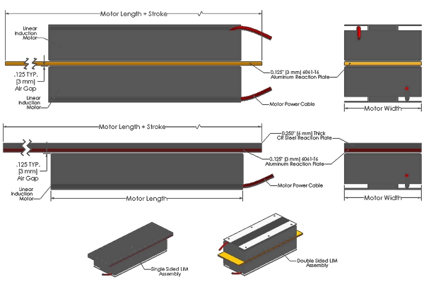
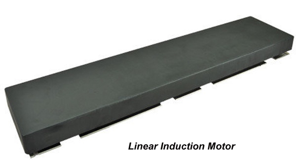
A linear induction motor (LIM) has a primary or coil assembly and a secondary or reaction plate.
The primary consists of three-phase coils wound and inserted into a steel lamination stack with thermal protection components.
At the same time, the secondary or conductive reaction plate includes a combination of a conductive metal like aluminum or copper and a magnetic steel backing that interacts with a traveling electromagnetic flux wave generated by applied three-phase AC power. The wave induces an electric current in the conductive reaction plate. The induced electric current interacts with the magnetic flux, producing linear force.

Typically, a bearing system gets designed to ensure a consistent gap between the primary and secondary. Maintaining a consistent gap will ensure a consistent force, because a linear induction motor's force will drop as the gap increases due to a reduction in the current induced in the reaction plate and a decrease in the magnetic field the farther away from the lamination stack.
Based on this premise, the secondary, ideally, would lie directly atop the primary. However, epoxy, varnish, or a case enclosing the primary coil assembly can require the user to have a more significant air gap, thus reducing the force.
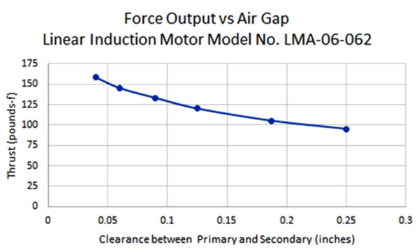
A real-world experiment shows that the correlation between the clearance gap and the output thrust is nearly linear. Figure 1 below shows this relationship. The results are consistent with modeling and calculations with regard to this relationship.

Most LIM designs begin with a design parameter of a 1/8-in. or 3-mm clearance between the primary coil and secondary reaction plate. This design parameter offers a feasible starting point, accounting for clearance taken up by epoxy or a case. If a larger clearance gap is needed, then this should be directed to the manufacturer to determine if a LIM with greater thrust should be designed for your application.

VIDEO: How does a linear induction motor work?
VIDEO: Example: Air bearing linear motor positioning stage ABS-012-12-030-X.
H2W Technologies is dedicated to the design and manufacture of linear and rotary motion products that are used in the motion control industry. The complete line of linear electric motors includes single- and dual-axis linear steppers, DC brush and brushless linear motors, voice coil actuators, and AC induction motors. Also offered is a complete line of ball screw, lead screw, and belt-driven positioning stages.
Other H2W Technologies motion control products include limited-angle torque motors for compact, limited-angular excursion rotary servo applications, 3-phase brushless rotary servo motors with matching digital servo amplifiers, and permanent magnet linear brakes for fail-safe, zero-power braking for baggage-handling and people-moving applications as well as amusement park rides.
With over 75 years combined experience in the linear and rotary motion field, the H2W Technologies team of engineers offers the optimal solution to the most demanding motion control requirements.
For additional information, contact Mark Wilson at H2W Technologies, 26380 Ferry Ct, Santa Clarita, CA 91350; Tel: 888-702-0540, E-Mail: info@h2wtech.com or visit the website at www.h2wtech.com.
Published October 2022
Rate this article
View our terms of use and privacy policy
