 |
| November 29, 2022 | Volume 18 Issue 44 |
Designfax weekly eMagazine

Archives
Partners
Manufacturing Center
Product Spotlight
Modern Applications News
Metalworking Ideas For
Today's Job Shops
Tooling and Production
Strategies for large
metalworking plants
How slip clutches can help maximize your designs
When design engineers think about slip clutches, they first think of using them for overload protection. While this is certainly a valuable application, there are a surprising number of other applications that solve many engineering problems. Slip clutches can be used for: increasing machine speeds; applying constant tension on paper, film, wire, threads, etc.; indexing a conveyor, table, or any mechanism; holding in position a lid, cover, screen, door, window, etc.; controlling torque for bottle capping, automatic screw assembly, closing valves, etc.; soft starts; cushioned stops; and many other applications.
Clutch operation
Depending on the application, the continuous slip clutch can give surprisingly long life - and at a surprisingly low cost as opposed to alternate methods of solving the engineering problem.
For continuous slip clutches, the torque range will go from oz-in. to 1,000 lb-in. Other much larger clutches are used for engage/disengage or for overload protection. The clutch capacity is dependent on the torque, rpm, and duty cycle, which are interdependent. A reduction in any of these will allow an increase in any other. The limit is based on heat buildup measured in watts, where:
Watts = Torque (lb-in.) x rpm x .011
Excess heat from higher-than-design wattage will shorten life. The friction plate design, when running within design limits, should operate for over 30 million cycles. In most cases, the clutch will outlast the mechanism it is in.
Applications
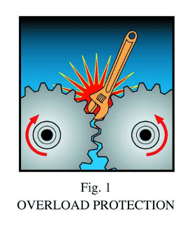
Overload protection
In general, the applications of slip clutches can be thought of as either "overload protection" (see Figure 1) or "all others," which covers a multitude of mechanisms.
For overload protection, the clutch can be anywhere from a shear pin to a ball detent to a friction plate design. The shear pin, of course, will operate only once, but it will effectively save the mechanism from damage. It must then be replaced.
The ball detent will slip at the set torque, with a pulsating torque going from zero to the designed break-away setting. Once the impediment is removed, it will function again for overload protection.
The friction plate design will slip at the break-away torque and give a constant, continuous torque at this setting. It will continue to slip until the impediment is removed. The basic design uses axial loaded plates and friction pads to transmit the torque. The higher the axial load, the higher the torque. This axial load is supplied mechanically by various spring arrangements. The load can also be applied pneumatically or electrically, in which case the torque can be changed during operation by varying the air pressure or the voltage. Servomechanisms can vary the torque to the needs of the mechanism. This feature also simplifies setup, as changes can easily be dialed in and repeated when needed. It is this continuous slip that opens up so many other applications.
Using "continuous slip" for cushioning/tension control
A good example is to use the slip clutch to increase the speed of the machine or mechanism. Slip clutches can be designed and manufactured so that the static friction is lower than the dynamic friction. This results in gradual application of torque and the cushioning of "suddenly applied loads." Tension on paper, thread, wire, film, etc. (Figure 2) is gradually applied and is half of the suddenly applied load. The machine can then run faster without overloading the material (Figure 3). The tension control is accurate, repeatable, cushioned, and durable. This cushioning is also felt throughout the machine, reducing the impact on gears, pulleys, slides, chains, etc., therefore allowing even higher speeds (Figure 4).
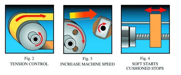
Applications of tension control vary from labeling machines to wire winding to film processing, thread control on knitting or sewing machines to all sorts of printing machines, to simple tension on a fishing rod, etc.
The tension can be applied by pulling the material around a roller as shown in Figure 2, or between two rollers as shown in Figure 5, or many other ways. As the material is pulled, it must make the roller turn and overcome the torque setting in the slip clutch, resulting in force F on the material. When the machine stops pulling, the force drops to zero. In some cases, the clutch can be turning slowly in the opposite direction, so that there is no slack and the force always remains at F, reducing the suddenly applied load even further.
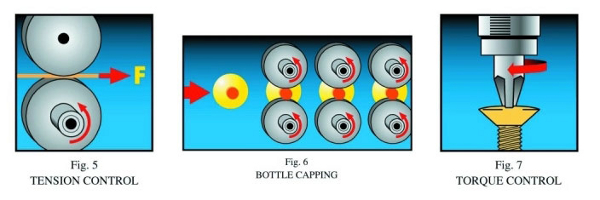
Higher machine speeds are only part of the story. Increased tool life is another. Just the cushioning effect (Figure 4) will prolong tool life considerably. But even more effective is removing the slippage of the tool against the product and handling this slippage within the clutch. A good example is in capping machines. These machines use a series of pairs of elastomer wheels to screw caps onto bottles as they come down the line (Figure 6). When the cap bottoms out, the old design used to let the wheels slip against the cap, resulting in damage to the product and shortening the life of the elastomer wheels. The newer designs let the wheels stop when the cap bottoms out. The slippage is all taken by the clutch, and this could be for well over 30 million cycles.
In addition to the increased tool life and less wear on the product, a more accurate torque is applied to the cap. This torque can be changed for different products. Also, by using pneumatic or electric actuation, the torque setting can be easily and repeatedly changed, with corresponding reductions in setup time and costs.
Similar applications include: automatically turning screws to a torque limit (Figure 7), closing valves, setting controls, and other torque-control operations.
Indexing
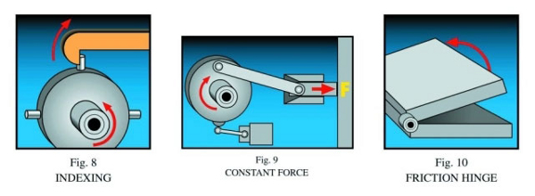
The continuous slip characteristic can also be used to index tables, conveyors, and other mechanisms (Figure 8). A simple index mechanism consists of holding a pin on an index wheel. The clutch slips continuously until a solenoid removes the hold, allowing the wheel to turn. The solenoid then returns the hold before the next pin arrives. This allows a single or partial revolution, and can be changed easily by moving the pins. Uneven indexes are easily programmed by moving the pins to uneven positions. This type of index mechanism is ideal for relatively low-speed, inexpensive indexing of tables, conveyors, controls, etc. Overload protection is obtained for free.
An interesting application of indexing is on vending machines. One motor can drive all the items, with an inexpensive slip clutch and solenoid holding back each item. When the item is selected, the motor goes on, but only the selected solenoid allows indexing to deliver that item. The motor then turns off until the next selection. The action is instant, for a short duration, and with little wear on the machine.
Force control
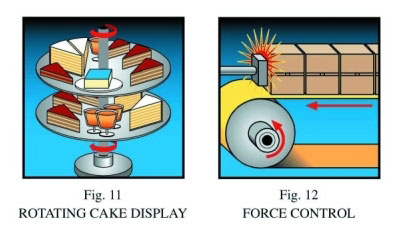
Pushing forces can also be generated by allowing a slipping clutch to push against a connecting force arm (Figure 9). This force control is used on ice machines to push a frozen tray into a "harvesting" cycle. When a single revolution is complete, it signals a new freezing cycle to begin. This inexpensive mechanism reduces cycle time considerably, which also saves energy. On conveyor applications (Figure 12), the transported product can push against a gate with no damage to the product or conveyor. All slippage is in the clutch. This also provides overload protection.
Pushing forces can also be generated by combining the slip clutch with a rack and pinion or belt and chain. Torque control can become either tension or thrust control.
Friction hinge
A popular and effective application is to use the slip clutch as a friction hinge (Figure 10). Installed at the pivot point, it will hold lids, covers, doors, windows, display screens, etc. at any position. When combined with a one-way clutch, there will be no resistance as the cover is raised, but the cover will remain at the desired position. Finger-tip force is all that is required to lower the cover. In applications where a "jerky" motion must be avoided, the smooth, cushioned slip clutch is needed.
Other applications
Of course, the slip clutch can be used in any application where a temporary stoppage is applied at random by just holding the mechanism. An example is a rotary cylinder used to display pastries at many restaurants (Figure 11). The cylinder is transparent or open and rotates slowly to present the pastries or other items. By just holding the cylinder, a pastry can be removed. Similarly, any moving mechanism such as conveyors, slides, rotary tables, etc. can be temporarily stopped, while the clutch does the slipping.
Slip at the end of the cycle is useful when a motor moves a mechanism into a locked position, such as closing a door or linear motion stops. Rather than having a time delay to keep the motor from burning up, a slip clutch can do the job for any length of time.
The range of applications for the slip clutch is vast. It has been used on robots to hold elements in the desired position. It has been used on automatic toilet seats, underground sewer pipe cleaning, airplane video screens, braiding machines, plotters, fiber optic cable systems, automatic doors, bar code printers, truck mirrors, etc.
In one unique application, the clutch had to accurately limit torque on a device that would clean out plaque within human arteries, without damaging the artery itself. Although the clutches were successfully developed and prevented any damage to the arteries, the program was eventually dropped. In this case, you might say that the operation was a success, but the patient died.
The applications for continuous or intermittent slip are limitless. Ingenious engineers come up with new uses every day. It is a practical and reliable way to solve real engineering problems -- a valuable tool in an engineer's arsenal.
Editor's note: Polyclutch became a brand entity of Dynatect Manufacturing, Inc., back in September 2014.
Source: Polyclutch
Published November 2022
Rate this article
View our terms of use and privacy policy